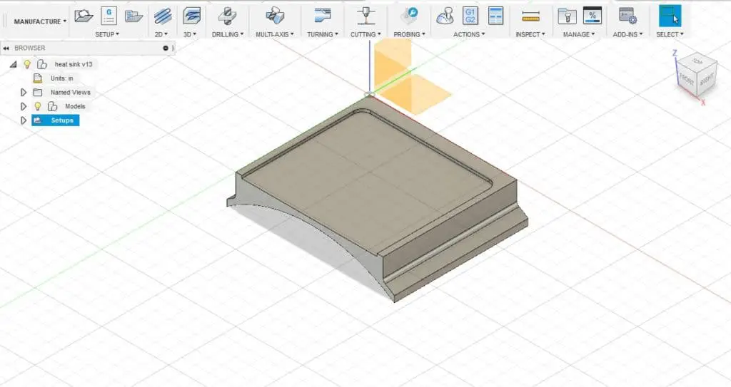

Inefficient, but does not affect the viability of the inlay. Use the mesh outline tools to trace the outline of the remaining material.
Save the result from Male (inlay) Op-3 simulation. If the artwork is simple enough use the offset tool in the sketch palette to generate the geometry. This can be crude, but the better (tighter) you make it the less wasted time. Draw a rough outline around your artwork at least StL outside the artwork. 
You can create this geometry a number of ways. This is a boundary that restricts Male (inlay) Op-4 from wasting a lot of time cutting air. NOTE: Stock Contours requires an additional geometry.
 Bottom height = “Top height”, offset = -DEPTH. Top height = “Selected contour”, offset = 0. Geometry = selected outline(s) from sketch. You can’t cut 0.3" deep with a bit that only has 0.25" flutes. Make sure the bit can handle the depth of cut. Tool = V-bit, 30/60/90 depending on inlay detail. Model = select the body that represents the part the pocket is cut into. Example: for a 60d V-Bit and a max depth of 3mm, StL = 0.577 x 3 = 1.731mm. StL, generic formula = tan(V-Bit/2) x DEPTH. The finer the details the narrower the v-bit needs to be to cut deep enough for the inlay to stick. Choose the engraving Bit (e.g., 60-degree V-Bit) based on inlay detail. Apparently, Imperials cut deeper inlays and Metrics cut shallower inlays. Typically, 0.3" or 3mm Yes, I know these are nowhere near the same. Choose the max depth of the inlay pocket (female part) = DEPTH. That’s not a requirement but if it’s not true then the Top Height values will need to change. These instructions assume the sketch containing inlay geometry (outline artwork) is coplanar with the surface to be cut. Base Decisions, Variables and Assumptions My recipe is based on the 3:2:1 formula found in many examples on YouTube. Note that a reasonable familiarity with Fusion 360 is a prerequisite for these instructions to make any sense. Here then is my recipe for creating v-carve inlays in Fusion 360. So when questions started coming up about Fusion in this forum, I dug my heals in and figured it out. But it bugged me that I couldn’t do the same in Fusion. It only takes me about a minute once I have artwork I like. Turns out, with their Advanced V-Carve function the inlays are trivial to set up. After failing to get a simulation that worked after several tries, I switched to Carbide Create, a free tool from Carbide3D. I quickly discovered that v-carve inlays are not so easy in Fusion.
Since I’ve been using Fusion 360 free for a couple of years now it was my tool of choice. Most of the time the YouTubers used Aspire. They look pretty cool so I thought I would try to create one. I was looking at YouTube videos that make v-carve inlays.


 0 kommentar(er)
